Location and Layout
Location: Mardella, South of Perth. Approximate lat/lon: -32.31, 115.96 degrees
Array layout: This is a text file containing the local east, north, height locations of antennas, in meters. ERA_asbuilt_ENU. (Note the heights in the file are all 0.0, but they are not sitting on the ground, they are about 1.8m above the ground mounted on poles.) ERA is currently a single polarisation system, and all antennas are aligned east-west.
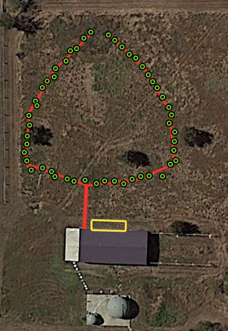
The google earth plan of ERA with antennas (green dots) and cable trays (red lines) is below. Drone footage is on the way!
System Design
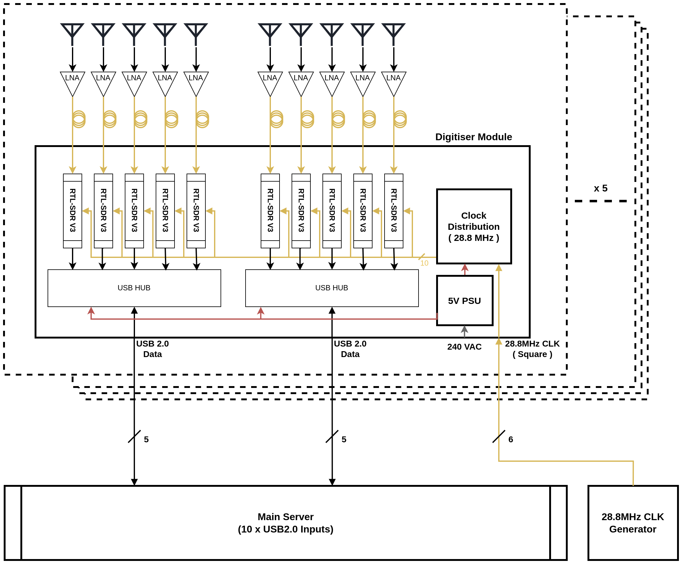
This is the block diagram of the ERA system.
Antennas
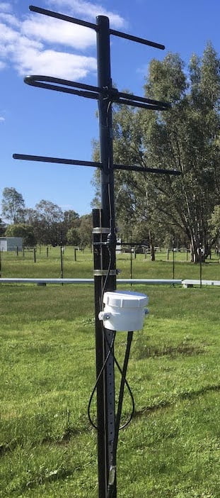
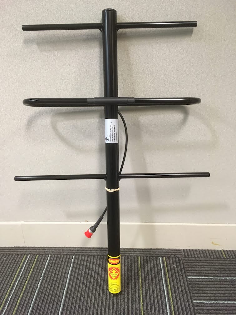
We use commercially available 3-element Yagi antennas from RF Industries, although they are available from many manufacturers. Simulations of the gain and radiation pattern are below.
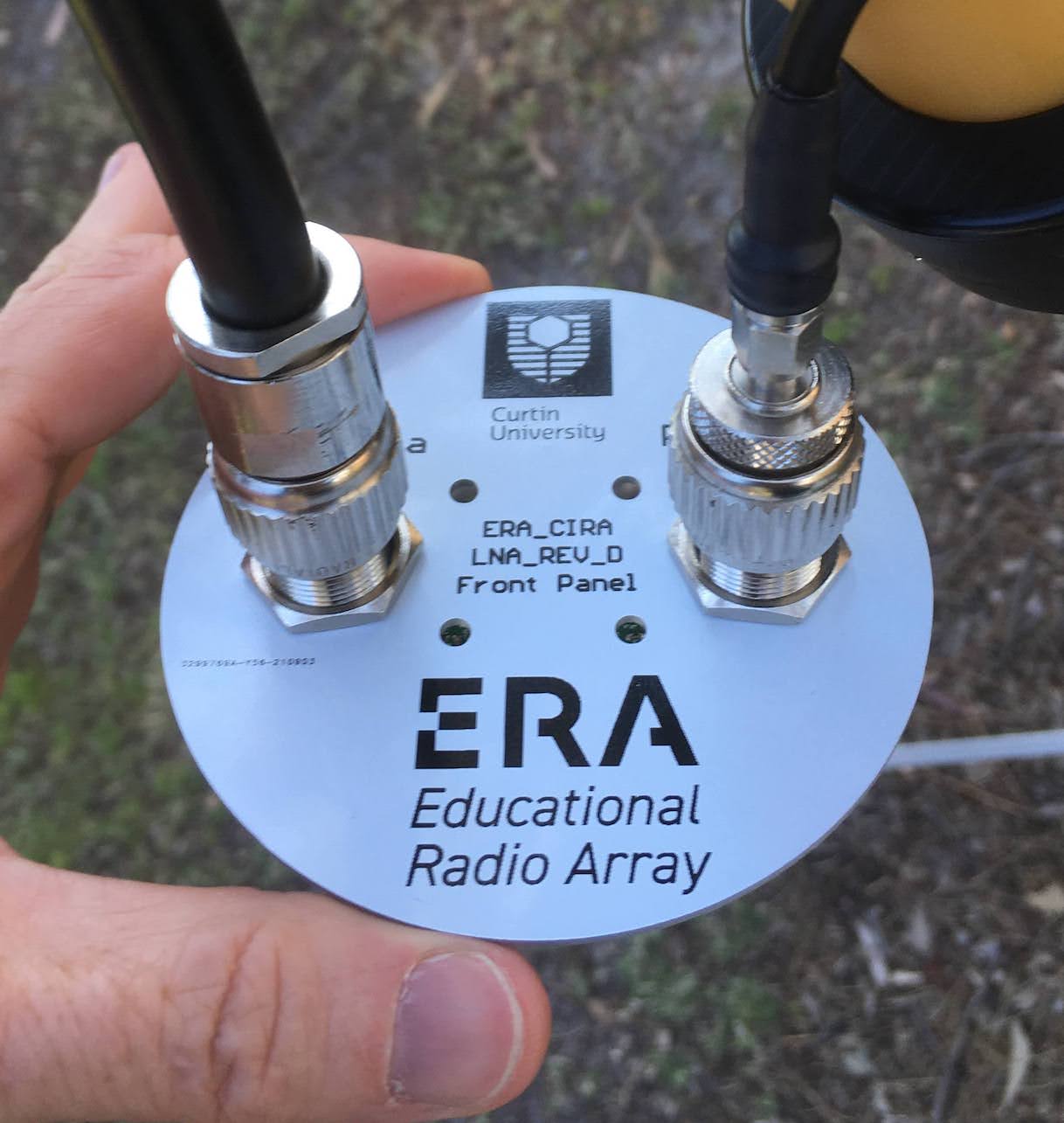
Low Noise Amplifiers (LNA)
We use in-house designed LNAs based around the minicircuits PSA4-5043+ monolithic amplifier chip. The LNA incorporates highpass filtering on the input to suppress broadcast TV and FM radio, and bias circuitry to power the LNA from 5V bias supplied on the coax cable that runs to the receivers.
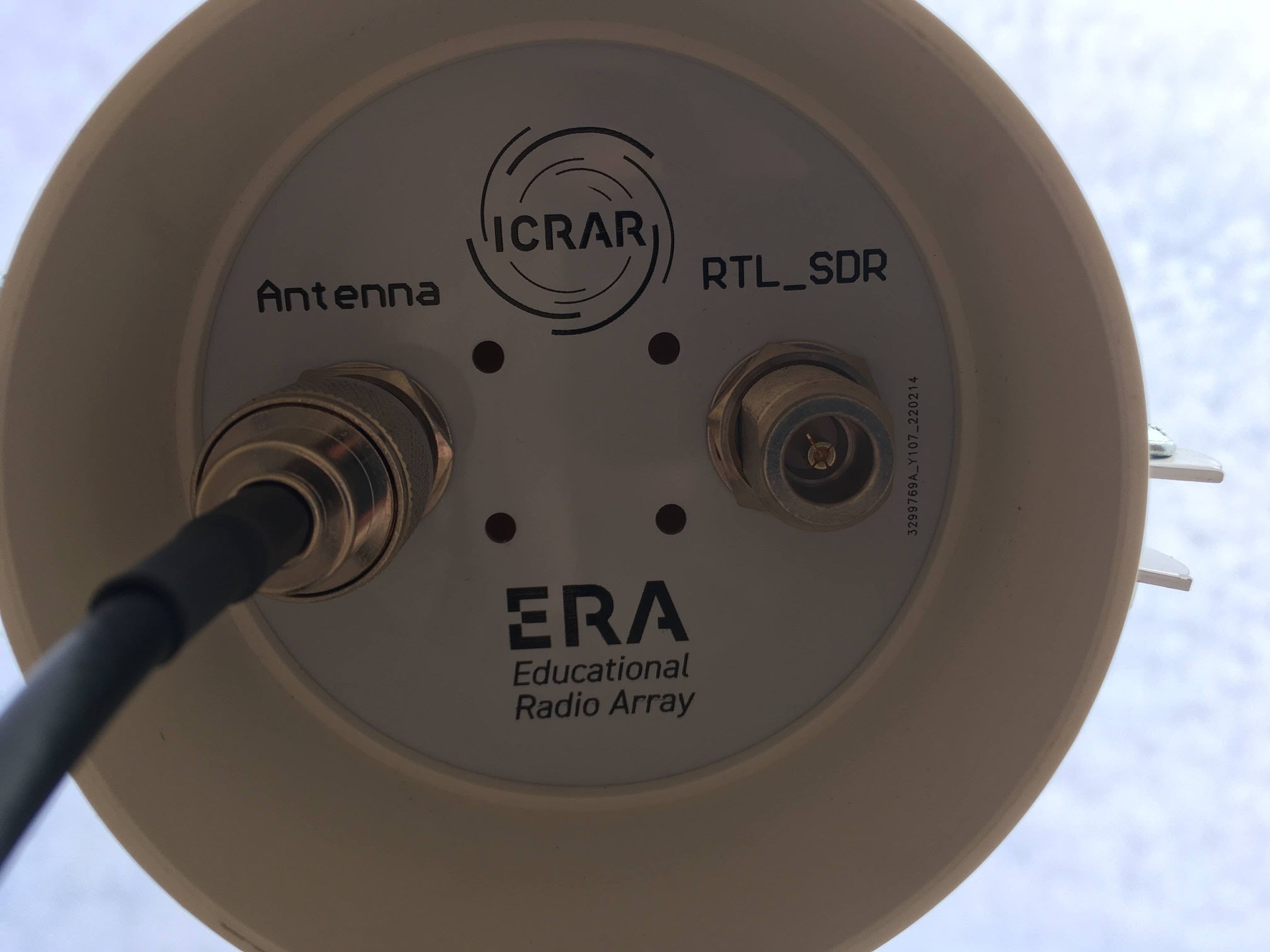

Receivers
ERA uses custom-built receivers based on COTS RTL-SDR modules that have been modified to accept an external clock reference. Each dongle digitises the signal from an antenna with up to 2 MHz of bandwidth.
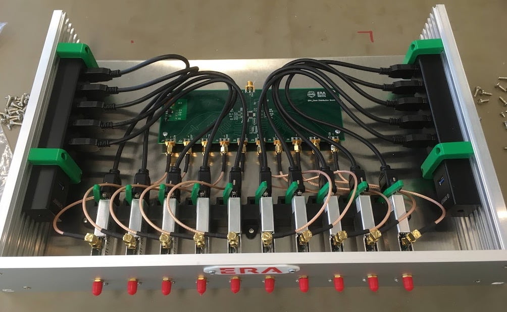
Each module contains
- 10 RTL-SDR receiver dongles
- 2 powered USB hubs
- custom-made clock fan-out board to reticulate the input clock to each dongle.
This is a photo of a partially assembled receiver with the dongles, USB hubs and clock fan-out board visible.
Sensitivity
The estimated sensitivity of ERA at 326 MHz is calculated below. Measuring the on-sky sensitivity is a work-in-progress.
- The antennas have a zenith gain of approximately 8.3 dBi at 326 MHz, hence a collecting area of 0.455 m2.
- The total system temperature including sky noise (not including the Sun or Galactic Centre) is estimated at 140K.
- Hence the antenna SEFD is 8.5 * 105 Jy.
The the overall system SEFD with 50 antennas is thus 17 kJy at zenith.